Operations Manual
Monkey
Hot Water Heater
Model # PWH-100/3
120VAC 60HZ 20AMP
Manufactured By: Custom Design &
Fabrication
Do Not Remove This Page
Read this Manual and Understand
Completely Before Start Up
Check System Function for Safety
Before Each Start Up
Do Not Use Heater Where System Failure
Could result in a Threat to Divers Life
Do Not Operate If Any Part of the System
Does Not Function Properly
Manufacturer and Distributors are not
Responsible for Misuse of this Equipment
Monkey Heater Specifications
The Monkey Hot Water Heater System is a complete, lightweight, portable, diver’s water heating system. The system uses a positive displacement submersible pump to provide water to the inlet side of the heater during operations. The system comes ready to operate with the exception of an electrical power source and fuel. The electrical power required to operate the system is 120 VAC, 60Hz, 20 amp, single phase.
The heating unit is mounted and enclosed in a steel, welded, square tubular frame, measuring 46” x 26” x 30.5”, weighing approximately 300lbs. The submersible water pump with a 25 foot umbilical is packed in the frame with the fuel tank. The heating unit is designed to operate on a 120 VAC, 60Hz, 20 amp, single-phase power source, using #1 or #2 diesel oil.
The unit is rated at 350,000 B.T.U. an hour output and is capable of heating the outlet water to temperatures in excess of 200° F., depending on the size of the fuel nozzle used and the inlet water temperature. The heater will maintain the set operating output temperature to +/- 1° F. Do not heat salt water is excess of 135 degrees F for it may crystallize inside the coils.
Fuel consumption is dependent on the size of the fuel nozzle in use. For example a 0.75 size nozzle will use approximately 3/4 gallons of fuel per hour, while a 2.0 nozzle will use approximately 2 gallons of fuel per hour.
Inlet water is provided to the heater by means of the 11-g.p.m. positive displacement submersible pump, provided with the system. The pump has a maximum combined pumping-lift head capability of 600 feet at 40 psi.
The submersible pump is designed to operate from a 120 VAC, 60Hz, 15 amp, single phase power source. A 15-amp switched outlet is mounted on the heater unit for use with the submersible pump only.
CAUTION !
It is required that the diver uses a hot water suit liner. This will help
to eliminate hot spots which could cause burns and provide
thermal protection in case of hot water heat loss.
Recommended Suit Injection Temperature
At
2 G.P.M. Flow Rate
For depths of 0 to 100 feet:
Water Temperature to 50° F. = 96° – 98° F.
Water Temperature to 30° F. = 100° – 102° F.
For Depths of 100 to 240 feet.
Water Temperature to 50° F. = 100° – 103° F.
Water Temperature to 30° F. = 103° – 105° F.
The recommended injection temperature is a base line and will need to be adjusted depending on the following factors.
a. Flow Rate (g.p.m.) to the diver. (Higher the rate, lower the temperature.)
NOTE!
The minimum recommended flow rate for 1/2 ID hose is 2 g.p.m. For 5/8” and 3/4” ID hose, the minimum recommended flow rate is 4 g.p.m.
b. Heat Loss from hot water hose.
NOTE!
The heat loss is dependent on: ID and OD of hose, length of hose, ambient air and water, and length of hose in the water.
c. Ambient water temperature.
d. Breathing medium.
e. Breathing gas temperature.
f. Physical condition of diver.
g. Work diver is performing
Hot Water Hose Heat Loss
On an average, the heat loss for a 300 foot, 1/2” ID, 1¼” OD hot water hose with an injection water temperature of 110° F. and a flow rate of 2 g.p.m., in an ambient water temperature of 35° F., will be about 18° F. (Base Line). The heat loss for a 1/2 ID, 7/8” OD hose, will be about 36° F. (Base Line).
Heat loss for the 5/8” and 3/4” ID hot water hose, under the same conditions, will be about 12° F. (Base Line).
If the flow rate is increased by 2 g.p.m., the heat loss will decrease by about 4° F. from the above base line temperature loss.
As the ambient water temperature increases, the heat loss will decrease. The percent of decreased heat loss to water temperature is 40° = 94%, 50° = 86%, 60° = 65%, and 70° = 40%.
Example
To figure the heat loss for a dive in 50° ambient water using 1/2” x 7/8” hot water hose, with a flow rate of 4 g.p.m.:
36° – 4° = 32° x 86% = 27.5° F. heat loss.
To figure what the heater output should be set at, add the recommended suit injection temperature and the hot water heat loss.
These figures are based on extreme ambient weather conditions. If the ambient air is warm, then heat loss will be less and heater output should be decreased.
Nozzle Size
Subtract input water temperature from the final recommended heater output temperature, multiply by the gallons per minute output, multiply by 510 (salt water) or 495 (fresh water), and divide by 100,000. Use the next smaller nozzle if answer does not come out to a nozzle size in the spare parts kit.
PUMP SET UP (Before Set-Up Procedures)
1. Remove pump from case.
2. Inspect the water tight electrical connection at the pump and the power cord for damage. If damage is evident, have a qualified electrician repair it before use.
WARNING!
DO NOT OPERATE ANY ELECTRICAL COMPONENT IN THIS SYSTEM WITHOUT USING A GROUND FAULT CIRCUIT INTERRUPTER (GFCI)
3. It is recommended that the pump is operated at a depth of 3 to 5 feet below Mean Low Water (MLW) or 2 feet from the bottom to prevent pump clogging.
WARNING!
DO NOT OPERATE PUMP IN THE VICINITY OF WORK LOCATION IF PUMPING CONCRETE OR OTHER HAZARDOUS MATERIALS ARE PRESENT IN THE WATER. SUCH MATERIALS CAN DAMAGE THE PUMP AND HEATER SYSTEM AND CAUSE SEVERE BURNS AND SKIN IRRITATIONS TO THE DIVER.
WARNING!
ALWAYS DISCONNECT THE PUMP FROM THE POWER SUPPLY BEFORE SET UP OR REMOVAL FROM THE WATER.
Set-Up Procedures
1. Set up the unit in the are to be used.
2. Pump must be plugged into the outlet provided on the unit, for the unit to function correctly.
3. Make all of the necessary connections.
a. Water from the submersible pump or other external source.
1. If external source is used, electric valve must be installed at the unit intake and connected to the power outlet provided. (Electric Valve must fail closed.)
b. Connect hose(s) from heater outlet valve(s).
WARNING!
DO NOT OPERATE ANY ELECTRICAL COMPONENT IN THIS SYSTEM WITHOUT USING A GROUND FAULT CIRCUIT INTERRUPTER (GFCI)
c. Electrical connections from a portable generator, 3kw minimum output or any other 120 VAC, 20 amp electrical source. The 15 amp electrical outlet provided on the back circuit panel box is for use with the submersible pump. ( 5kw generator is recommended.)
4. Fuel unit with either #1 or #2 diesel oil.
5. Make sure a flow of water is present through the system.
WARNING!
NEVER OPERATE THE FUEL PRESSURE AT THE REGULATOR LESS THAN 100 PSI. FAILURE TO OBSERVE THIS WARNING WILL RESULT IN INCOMPLETE COMBUSTION, CAUSING EXCESSIVE COIL SOOTING, HARMFUL VAPORS, EXCESSIVE SMOKE AND POSSIBLE FLASHING.
6. Turn unit on, check to make sure burner has fired, and temperature display is functioning.
a. Test flow switch.
b. To properly test flow switch function, shut down the water flow to the heater. The unit should shut down if the switch is functioning properly.
NOTE
Once burner has fired, observe smoke color. If smoke is white, slightly close vent opening on the burner assembly until smoke disappears. If smoke is black, reverse procedure, slightly opening vent until smoke disappears.
7. Crack open by-pass valve. Set the water flow pressure at 10 psi., using the valve at the units water inlet.
8. Set fuel pressure at the fuel regulator to 120 psi.
9. Allow unit to run 5 minutes or until temperature remains constant on the digital display.
NOTE
Starting operating temperature is recommended to beat 100° F. and is only a guideline for starting procedure. Fine-tuning of the temperature will be when in actual use. It can be set or changed using the water flow controls or the fuel pressure, set at the regulator.
WARNING!
DO NOT OPERATE THE SYSTEM WITHOUT A DIVER BY-PASS VALVE THAT CAN BE OPERATED BY THE DIVER TO ELIMINATE WATER FLOW IF NECESSARY. IN THE EVENT OF A UNIT MALFUNCTION, SEVERE BURNS MAY OCCUR.
10. Once a comfortable working temperature has been achieved, fine adjustments can be made at the fuel pressure regulator.
11. If all set-up procedures have been followed, you should be able to maintain your operating temperature at +/- 1° F.
HIGH-POINT TEMPERATURE CUT-OFF
After temperature has remained constant on the digital display for 3 minutes, depress the set point button on the control panel. This changes the display to read the present high-point temperature cutoff temperature. Adjustments can be made as follows:
For the primary digital readout
A. Press the center button and release. The display will read SP, wait approximately two seconds, press the up or down button and the set points will be displayed.
B. Press and hold the up or down button until the desired set point is displayed.
3 degrees F over the working temperature is recommended.
C. Wait approximately 10 seconds. If the set pint was changed, the display will flash then the SPC will return to display the sensor temperature. (If you do not want to wait 10 seconds, press the center button once to adjust the differential or press the center button twice to immediately display the sensor temperature.)
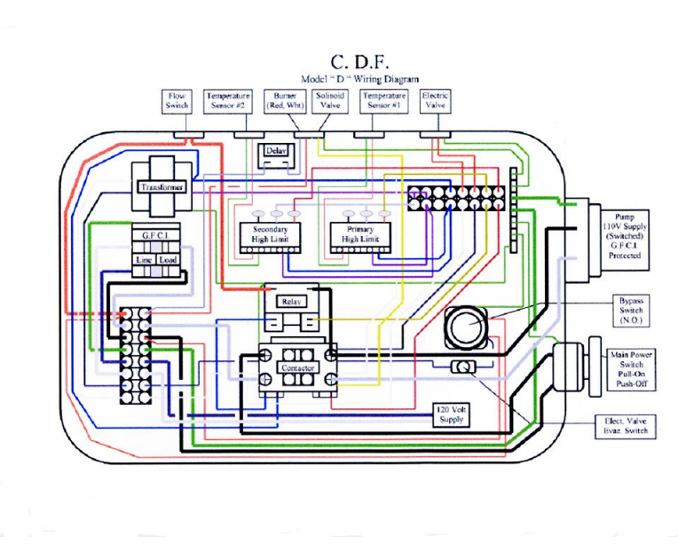
For your added safety C.D.F. has installed a Secondary High Limit Circuit. This circuit will trip the unit, the pump receptacle, and stop water flow through the unit in the event of a secondary high-limit trip.
NOTE!
IF THE SECONDARY HIGH LIMIT CIRCUIT TRIPS THE WATER TEMPERATURE IN THE SYSTEM MUST DROP 15 DEGREES F BEFORE THE SYSTEM WILL RESTART
The secondary high limit should be calibrated with the primary at the beginning of each dive day or at each time the unit is restarted. Follow the operations manual start up procedures as always and follow these additional steps:
A. After a constant divers working temperature has been achieved set the primary high-limit as described in the manual.
B. Set the secondary high-limit in the same manner as the primary, changing the set point temperature to 5 degrees F over the working temperature instead of 3 degrees F.
C. Complete the remaining daily safety systems checkout as described in this operations manual.
WARNING!
SUPPLY PUMP MUST BE CONNECTED TO THE OUTLET PROVIDED ON THE UNIT FOR THE SECONDARY HIGH
LIMIT TO FUNCTION CORRECTLY.
WARNING!
HIGH-POINT CUT-OFF TEMPERATURE SHOULD BE SET NO HIGHER THAN 2°- 3° F. MAXIMUM OVER WORKING TEMPERATURE TO PREVENT INJURY TO THE DIVER. FAILURE TO OBSERVE THIS WARNING COULD RESULT IN HEAT EXHAUSTION OR SEVERE BURNS TO THE DIVER.
WARNING!
ALWAYS KEEP CONTROL PANEL COVER CLOSED DURING INCLEMENT WEATHER TO PREVENT DAMAGE TO ELECTRICAL COMPONENTS IN THE SYSTEM.
WARNING!
SHOCK HAZARD! DO NOT TOUCH ANY ELECTRICAL COMPONENTS IN THIS SYSTEM WHEN WET. SEVERE SHOCK OR ELECTROCUTION COULD OCCUR.
WARNING!
COMBUSTIBLE MATERIAL PRESENT. KEEP AWAY FROM SPARK OR OPEN FLAME.
FUEL HOOK-UP PROCEDURE
1. Portable fuel containers are provided for your convenience. Each fuel tank has quick connect snap fittings.
2. Connect fuel hose to the tank. Connect the fuel by-pass line to the female quick disconnect
3. OPEN FUEL VENT ON THE FILLER CAP.
4. Unit is self-priming.
SHUTTING THE SYSTEM DOWN
1. Shut the heater off at the control panel.
2. Allow the submersible pump to run until outlet water temperature is between 80° – 90° F.
3. Shut off and unplug the submersible pump.
3. Remove the pump from the water and disconnect all pump fittings. Invert the pump to remove all water.
5. Submerge the pump in a BIO safe solution of anti-freeze.
6. Reconnect the pump to the power supply to flood the system with antifreeze. (Pump umbilical and unit require approximately three gallons of antifreeze.)
7. Free divers umbilical of water and/or flood with anti-freeze. (An evacuation unit can be used to simplify this procedure. Evacuation units are available in 3 or 6-gallon capacities.)
DAILY MAINTENANCE
1. Always check high point cut-off setting on display to ensure that it is properly set, 2 – 3 degrees F above the working temperature
2. Check outlet water temperature to verify that sensor is functioning properly.
3. Calibrate secondary high limit 3 – 5 degrees F above working temperature
4. Test trip your safety valve.
NOTE
These daily checks will ensure the unit is functioning correctly.
WARNING!
DO NOT OPERATE UNIT IF ANY COMPONENT IN THE SYSTEM IS NOT FUNCTIONING CORRECTLY. TO DO SO COULD CAUSE SEVERE BURNS TO THE DIVER OR CAUSE DAMAGE TO THE SYSTEM.
WEEKLY MAINTENANCE
1. Disconnect Power Supply
2. Replace any non-working parts, valves, gauges etc.
3. Review safety checklist for unit function.
4. Change fuel filter.
WARNING!
WHEN SERVICING, BE SURE HEATER IS DISCONNECTED FROM POWER SOURCE TO PREVENT ELECTRICAL SHOCK OR FIRE.
MONTHLY MAINTENANCE
1. Disconnect Power Supply.
2. Replace any non-working parts.
3. Review safety checklist for unit function.
4. Change fuel filter.
5. Replace fuel nozzle
6. Inspect coils for soot build up.
7. Inspect fuel tank and fittings for dirt and water inside.
8. Inspect electrodes for damage.
9. Inspect circuits for corrosion and damage through the see-through widow.
Do not remove switch panel
YEARLY MAINTENANCE
1. Change fuel filter.
2. Change fuel nozzle.
3. Inspect blower for corrosion.
4. Wash heater coil free of soot, using a wire brush or vacuum.
5. Remove 3 nuts from burner mounting flange.
6. Carefully remove burner and set aside. Leave electrical connections and
fuel hose intact.
7. Cover with waterproof plastic.
8. Replace gasket on burner flange.
9. Check parts inventory.
a. New fuel filter.
b. Replace lost or used fuel nozzles.
c. Replace hose fitting washers.
d. Replace any lost or worn fittings.
WARNING!
DO NOT OPEN ELECTRICAL CLOSURE FITTINGS OR PANEL COVERS. THIS PROCEDURE SHOULD ONLY BE DONE BY A QUALIFIED ELECTRICIAN.
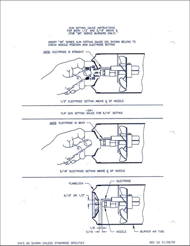
NOZZLE CHANGING PROCEDURE
1. Disconnect Power Supply.
2. Close air vent on burner adjustment band.
3. Loosen the flare nuts and remove the fuel line between the solenoid valve and nozzle pipe. Set aside. Caution! Be careful not to drop the nut into the air vent!
4. Remove nozzle pipe retaining nut from nozzle pipe and set aside.
5. Loosen the coil clamp located on the other side of the coil and open the burner lid. Carefully slide the nozzle pipe assembly downward and out until the assembly becomes free and lifts out.
Caution! Be careful not to damage the ceramic insulators on the electrodes.
6. Replace the nozzle with the desired size.
7. Reset the electrodes or replace if damaged.
8. Replace the nozzle pipe assembly. Re-assemble all components by reversing the disassembly procedures. Open air band on the burner assembly. Make air adjustments following set-up procedures.
BE CAREFUL NOT TO MOVE ELECTRODE SETTINGS
TROUBLESHOOTING
1. No water flow.
a. Check connection at outlet.
b. Pump may be frozen.
c. Pump may be burned out.
d. Check electrical circuit.
e. Check secondary high limit adjustment.
2. GFCI keeps tripping. (LED blinks, clicking sound is heard.)
a. Pump may be frozen.
b. Power surge.
c. Short in circuit.
d. Insufficient power supply.
3. Black smoke.
a. Not enough air.
b. Faulty solenoid valve.
c. Dirty fuel.
d. Electrodes misaligned.
e. Weak high voltage coil. (clean contacts.)
4. White smoke.
a. Too much air.
b. Not enough fuel.
5. Relay indicator blink. (Clicking is heard.)
a. Not enough electrical power. (Minimum 110 VAC.)
6. No fuel pressure.
a. Faulty regulator.
b. Clogged fuel filter.
c. Clogged fuel line.
d. Snap fitting not coupled properly.
e. Leak in fuel line or prime bulb.
f. Vent cap closed on fuel tank.
7. Burner won’t fire.
a. Same as above for fuel pressure.
b. Electrodes misaligned.
c. Weak voltage coil / dirty contacts.
d. Cracked ceramic on electrodes.
e. Water in fuel.
f. Not enough electrical power. (Minimum 110 VAC.)
g. Re-set button tripped. (Located on motor case.)
8. Snap fitting leak.
a. Replace o-ring.
b. Replace fitting.
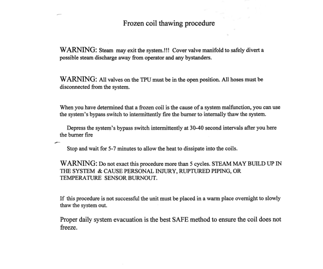
9. System freezes.
a. Shut system off. Turn pump off.
b. Slowly thaw with forced air heat.
WARNING!
DO NOT ATTEMPT TO THAW WITH OPEN FLAME
10. Overheating.
a. Faulty sensor.
b. Faulty relay(s).
c. Insufficient flow of water. (Check flow requirements for size of hose.)
11. Underheating.
a. Too much water flow. (Check flow requirements for size of hose.)
b. Low fuel pressure. (120 psi at the regulator.)
c. Fuel nozzle too small.
d. Soot on coil.
12. No PSI on manifold.
a. Open gate valve.
b. System frozen.
c. Cracked coil.
13. No power to heater.
a. Check electrical connection.
b. Push system by-pass switch.
WARNING!
IF SYSTEM FIRES, THERE IS A FAULTY CIRCUIT.
DO NOT OPERATE!
14. LED erratic.
a. Faulty sensor.
b. Damp circuit. (Dry with forced air heat.)
c. Fluctuating supply water pressure.
15. Fuel tank collapse.
a. Open tank vent.
b. Vent may be plugged.
16. Low water pressure.
a. Insufficient water supply.
b. Kink or obstruction in water hose.
c. Pump by-pass opened too much.
17. Fuel pump won’t prime.
a. Obstructed fuel line.
b. Air leak in fuel line.
c. Fuel filter cap loose.
d. Faulty fuel pump.
18. Drip from bottom of combustion chamber.
Note! Check smell and/or feel of liquid
If diesel is present:
a. Faulty solenoid valve.
b. Loose nozzle.
c. Misaligned electrodes.
If diesel is not present:
a. Normal condensation from coil.
19. Motor hiss.
a. No lubrication in motor.
20. Thermal re-set on the motor trips.
a. Snap fittings on the fuel supply are not correctly engaged.
b. Fuel pump is not functioning.
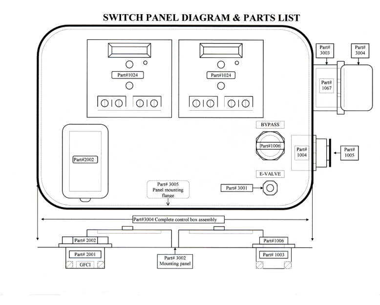
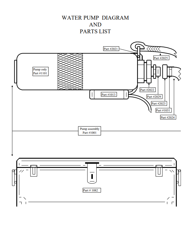
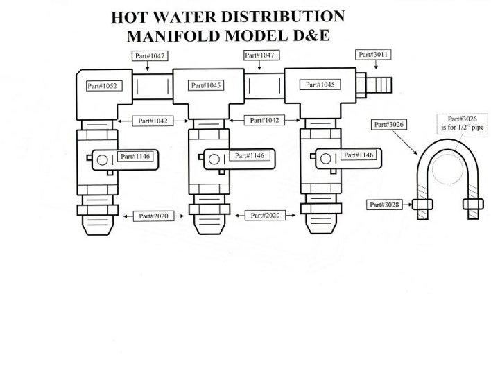
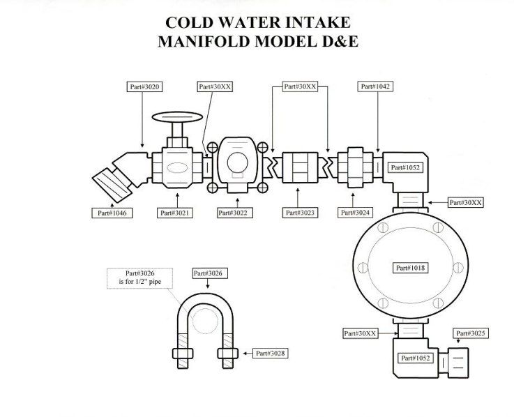
PARTS LIST
| ITEM# | DESCRIPTION |
|---|---|
| 1001 | SUBMERSIBLE PUMP WITH UMBILICLE |
| 1001B(1101) | SUBMERSIBLE PUMP ONLY |
| 1003 | NORMALLY OPEN SWITCH MODULE |
| 1004 | NORMALLY CLOSED SWITCH MODULE |
| 1005 | MUSHROOM PULL SWITCH BODY |
| 1006 | MOMETARY SWITCH ON BODY |
| 1007 | LIQUID TIGHT STRAIGHT CONDUIT CONNECTION 1/2 INCH |
| 1008 | LIQUID TIGHT 90 DEGREE CONDUIT CONNECTION 1/2 INCH |
| 1009 | 90 DEGREE ELECTRICAL BOX LEFT 1/2 INCH |
| 1010 | BOX COVER |
| 1011 | COVER GASKET |
| 1013 | WATER TIGHT SPLICE KIT |
| 1015 | ELECTRICAL BOX TEE 1/2 INCH |
| 1016 | 15 AMP MALE ELECTRICAL CONNECTOR 110 VOLT |
| 1017 | LEXAN SWITCH PLATE 1/4 INCLUDE |
| 1018 | FLOW SWITCH 1/2 INCH |
| 1019 | FUL-FLO FUEL FILTER |
| 1020 | FUL-FLO FILTER REPACEMENT CARTRIDGE |
| 1021 | DELAYED MAG VALVE |
| 1021B(1121) | MAG VALVE NEMA-4 ENCLOSURE |
| 1022 | SINGLE POLE SINGLE THROW RELAY |
| 1023 | 24 x 110 VOLT TRANSFORMER |
| 1024 | DIGITAL READOUT WITH SENSOR |
| 1024B(1102) | TEPERATURE SENSOR (PRIMARY) |
| 1025 | NOSE ASSORTMENT 80 DEGREE NS |
| 1025B | |
| 1026 | GAUGE 0-100 PSI |
| 1027 | FLANGE GASKET |
| 1028 | COIL BURNER ASSEMBLY |
| 1029 | OIL ASSEMBLY |
| 1030 | 3/8 INC STAINLESS STEEL BAND |
| 1031 | 1/2 INCH BARB x 3/4 INCH GARDEN HOSE FEMALE |
| 1032 | 1/2 INCH ID-300 WORKING PRESSURE HOSE |
| 1033 | LABLE PACKAGE |
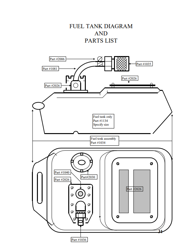
| 1034 | FUEL TANK (SPECIFY SIZE) |
| 1035 | FEMALE QUIK DISCONNECT 1/4 INCH |
| 1036 | MALE QUICK DISCONNECT 1/4 INCH NPT |
| 1037 | PRIME BULB |
| 1038 | 1/2 INCH BRONZE GATE VALVE |
| 1039 | 1/2 90 DEGREE STREET ELBOW BRASS |
| 1040 | 1/4 INCH BARB x 1/4 INCH MALE NPT BRASS |
| 1041 | 1/2 INCH BARB x 3/8 INCH MALE NPT BRASS |
| 1042 | 1/2 INCH CLOSE NIPPLE BRASS |
| 1043 | 1/4 INCH 90 DEGREE STREET ELBOW BRASS |
| 1044 | 1 1/4 INCH x 3/4 INCH BUSHING BRASS |
| 1045 | 1/2 INCH FULL FEMALE T BRASS |
| 1046 | 3/4 INCH GH x 1/2 INCH NPT BRASS |
| 1046B(1146) | 1/2 INCH IPS BALL VALVE BRASS |
| 1047 | 1/2 INCH x 3 1/2 INCH LONG NIPPLE BRASS |
| 1050 | 1/2 INCH x 1/4 INCH BUSHING BRASS |
| 1051 | 3/8 INCH NPT x 1/4 INCH HOSE BARB BRASS |
| 1052 | 1/2 INCH FULL FEMALE 90 DEGREE ELBOW BRASS |
| 1053 | 1/2 INCH x 2 INCH LONG NIPPLE |
| 1054 | 1/2 INCH x 11 INCH LONG NIPPLE BRASS |
| 1055 | 3/16 INCH FLARE NUT BRASS |
| 1056 | FLARE BY MALE ELBOW BRASS |
| 1057 | FLARE BY MALE STRAIGHT CONNECTOR BRASS |
| 1058 | 1/4 INCH x 3/16 INCH BUSHING BRASS |
| 1059 | 1/4 INCH HOSE BARB x 1/2 INCH FEMALE NPT BRASS |
| 1060 | 1/4 INCH HOSE BARB x 1/4 INCH FEMALE NPT BRASS |
| 1062 | PRIMARY SENSOR WET WELL |
| 1063 | ELECTRICAL CONDUIT 1/2 INCH NON METALIC PER FOOT |
| 1064 | ELECTRICAL CONDUIT 1/2 INCH NON METALIC PER FOOT |
| 1065 | ELECTRICAL CONDUIT 1/2 INCH NON METALIC PER FOOT |
| 1066 | ELECTRICAL CONDUIT 1/2 INCH NON METALIC PER FOOT |
| 1067 | 120 VOLT RECEPTICE 15 AMP |
| 1068 | FUEL REGULATOR ASSEMBLY |
| 1068B(1168) | 0-200 FUEL GAUGE |
| 1069 | MANAFOLD FEED HOSE |
| 1072 | PUMP UMBILICAL |
| 1073 | CHASSIS |
| 1074 | FUEL LINE FEED 1/4 INCH PER FOOT |
| 1075 | FUEL PUMP FEED PER FOOT |
| 1076 | FUEL BYPASS LINE PER FOOT |
| 1077 | FUEL REGULATOR INLET |
| 1078 | FUEL REGULATOR DISCHARGE |
| 1079 | FUEL BURNER FEED |
| 1080 | FUEL TANK CAP |
| 1081 | BYPASS CONNECT HOSE PER FOOT |
| 1082 | PUMP CARRY CASE |
| 1083 | JUNCTION BOW ASSEMBLY |
| 1084 | UNIT ELECTRICAL FEED |
| 1085 | BURNER TRANSFORMER |
| 1086 | BURNER MOTOR |
| 1087 | FUEL PUMP (1ST STAGE) |
| 1087B(BUS) | FUEL PUMP (2ND STAGE) |
| 1088 | BURNER MOUNT NUT |
| 1089 | SWITCH BOX ASEMBLY |
| 1090 | SECONDARY HIGH LIMIT CONTROLLER |
| 1091 | SINGLE PURPOSE CONTACTOR |
| 1093 | 110 VOLT DELAY (MINIMUM 6 SEC) |
| 1094 | SECONDARY HIGH LIMIT COVER |
| 1095 | 1/2 INCH 3 HOLE ELECTRICAL C0VER |
| 1096 | SECONDARY SENSOR CONDUIT CONNECTION |
| 1097 | SECONDARY SENSOR CONDUIT 1/2 INCH NON METALIC PER |
| 1098 | FOOT 1/2 INCH 3 HOLE 2×4 ELECTRICAL BOX OUTDOOR |
| 1099 | SRAIN RELIEF CONNECTION 1/2 INCH |
| 2000 | WEATHER TIGHT SINGLE 20 AMP RECEPTACLE COVER |
| 2001 | MOTOR CONTROL GFCI |
| 2002 | GFCI COVER OUTDOOR NON METALIC |
| 2003 | ELECTRODE CERAMIC |
| 2004 | ELECTRODE TUNSGON ONLY |
| 2005 | FUEL DELIVERY TUBE |
| 2006 | HOSE CLAMP |
| 2007 | NOZZLE HOLDER |
| 2008 | AIR DAM |
| 2009 | WATER TIGHT THERMAL RESET COVER |
| 2010 | AIR MIX ADJUSTMENT BAND |
| 2011 | BULKHEAD CONNECTOR |
| 2012 | BULKHEAD CONNECTOR RETAINING NUT |
| 2013 | SQUIRREL CAGE FAN |
| 2014 | DRIVE SHAFT |
| 2015 | 1/2 INCH FULL FEMALE CROSS |
| 2016 | 1/2 INCH NPT x 1/2 INCH SLIP CONNECT WET WELL |
| 2017 | TEMPERATURE SENSOR (SECONDARY) |
| 2018 | 1/2 INCH FEMALE COUPLER |
| 2019 | ELECTRICAL CONDUIT 1/2 INCH NON METALIC PER FOOT |
| 2020 | 1/2 INCH NPT x 45 DEGREE BEVEL |
| 2021 | STAINLESS STEEL SHACKLE |
| 2023 | 1/2 INCH BARB x 3/4 INCH FEMALE GARDEN HOSE BRASS |
| 2024 | 3/4 INCH 300 POUND WORKING PRESSURE WATER HOSE PER |
| 2025 | 3/8 INCH POLYPRO ROPE PER FOOT |
| 2026 | FIBERGLASS “DANGER- DEISEL FUEL”TANK LABEL |
| 2027 | FUEL SENDING TANK UNIT |
| 2028 | FUEL REGULATOR MOUNTING BRACKET |
| 2029 | 3/4 INCH NPT x 3/4 INCH GARDEN HOSE MALE ADAPTOR |
| 2030 | FUEL TANL FILL CAP |
| 2031 | END CAP BURNER |
| 2032 | END ACAP DISCHARGE |
| 2033 | OVERSEAS PARTS BOX |
| 2034 | OVERSEAS PARTS KIT |
| 2035 | STEP DOWN TRANSFORMER |
| 2036 | WHEEL KIT |
| 2037 | 25 GALLON TANK MOBILE |
| 2038 | 50 CYCLE CONVERSION KIT WITH SPARES |
| 2039 | INTEGRAL EVACUATION (PNEUMATIC) |
| 2040 | SECONDARY SENSOR MODEL C |
| 2041 | BUCKET EVACUATION RESEVOIR (FREE STANDING) |
| 2042 | FUEL SOLENOID VALVEAND BURNER ISOLATION SWITCH ( 2 ) |
| 3000 | MODEL D/E CHASSIS |
| 3001 | EVACUATION SWITCH (MOMENTARY) |
| 3002 | CONTROL PANEL ONLY (LEXAN PLATE) |
| 3003 | 2×4 SINGLE OUT PVC ELECTRICAL BOX |
| 3004 | CONTROL SWITCH ASSEMBLY (COMPLETE) |
| 3005 | PANEL FLANGE |
| 3006 | LARGE BARRIER STRIP |
| 3007 | SMALL BARRIER STRIP |
| 3008 | GROUND BAR |
| 3009 | CONTROL BOW ASSEMBLY WITH COMPONENTS |
| 3010 | PUNCH CONTROL BOX ONLY |
| 3011 | 1/2 INCH NPTM x 1/2 INCH BARB |
| 3012 | 1/2 INCH NPTM x 1/2 INCH JIC 45 DEGREE |
| 3013 | 1/2 INCH LONG NIPPLLE ORDER BY MEASUREMENT |
| 3014 | 1/2 INCH X 3/4 INCH BUSHING |
| 3015 | 3/4 INCH FFM TEE |
| 3016 | 3/4 INCH NIPPLE 2 INCH |
| 3017 | 3/4 INCH 45 DEGREE STRAIGHT ELBOW |
| 3018 | 3/4 INCH NPTM x 1/2 INBCH BARB |
| 3019 | TEMPATURE SENSOR WET WELL |
| 3020 | 1/4 INCH 45 DEGREE ELBOW |
| 3021 | 1/2 INCH GATES VALVE |
| 3022 | 1/2 INCH WATER SOLNOID VALVE |
| 3023 | 1/2 INCH HEX COUPLER |
| 3024 | 1/2 INCH UNION |
| 3025 | 1/2 INCH STEP UP |
| 3026 | 1/4 INCH / 20 STAINLESS STEEL U-BOLT (1/2 INCH PIPE) |
| 3027 | 1/4 INCH FLAT WASHER |
| 3028 | 1/4 INCH /20 SAINLESS STEEL NYLOCK NUT |
| 3029 | 1\4 INCH / 20 STAINLES STEEL U-BOLT (3/4 INCH PIPE) |
| FRK100/3 | MONKEY HEATER SPARE PARTS KIT |
| HWDHM | DUAL HEATER MANIFOLD |
FUEL FILTER PRIMING PROCEDURE
REGULATIONS REQUIRE SYSTEMS TO BE SHIPPED FREE OF
COMBUSTABLES
THE FUEL FILTER MUST BE FILLED WITH DIESEL BEFORE
THE UNIT IS PUT INTO SERVICE. THIS IS REQUIRED THE
FIRST TIME THE UNIT IS PUT INTO SERVICE
1. Remove large filter cap nut using an adjustable wrench. *Note: Be careful not to misplace nut sealing gasket
2. Set filter cap retaining nut aside
3. Remove filter top. *Note: Do not misplace rubber gasket
4. Fill filter body completely with clean diesel fuel allowing time for element to saturate filter
5. Replace rubber filter housing gasket
6. Reinstall filter housing lid
7. Reinstall large filter cap nut. *Note: Place sealing gasket under capnut
8. Tighten securely
9. Upon starting unit the first time, observe the air bubbles in the clear fuel line located on the output side of fuel filter. The air bubbles should dissipate in a few minutes. If air bubbles do not dissipate
9a. Check rubber gasket position
9b. Tighten filter cap bleed nut
9c. Tighten large filter cap nuts
9d. Check QD fittings are secure
9e. Tighten all flexible fuel line screw clamps
Testing A Heater
1. Hook up water and check Airband
2. Plug in machine
3. Hook up fuel lines
4. Put on discharge hose
5. Open discharge
6. Make sure bypass is closed
7. Open water in gate
8. Turn on water
a. Load regulator about 2 ½ turns
9. Turn on unit
10. Check GFI
11. Check electric valve
a. Water should flow
12. Wait for output light to come on
13. Red lights come on
a. Check temperature, both should be within 1-2 degrees
of each other
b. Unit must level
14. Set secondary differential to 15
15. Set secondary set point to 125
a. Output light should come on
i. Contactor should close
16. Set primary differential to 2
17. Set primary set point to 120
18. Check flow switch by turning off water using gate valve
a. Unit should shut down
19. Turn water back on
a. Unit should fire in 6 seconds
20. Fuel pressure should be 100
a. No smoke
i. If black, open air 1/8” increments
ii. If while close 1/8” increments
21. Calibrate fuel pump to 200
a. Close regulator, dial up clockwise, pump with 1/8 allen
to 200
b. Dial regulator back up and allen up 200
i. Shouldn’t be able to pass
22. Dial back to 100
a. Check for fuel leaks
23. Check secondary
a. Dial down until unit shuts off
i. ALL functions should stop
ii. No flame
iii. No water
24. Dial secondary set point back up
a. Unit should resume operation to 120-125
b. Let unit run and let temperature level out
i. Should be within 2 degrees
c. If unit cycles raise primary and secondary SP 5 respectively until unit stops cycling hot exceed 170 on
secondary
25. Reset primary SP to 120
26. Recheck differential to make sure it is 2
a. Burner should shut off
27. Reset secondary SP to 125
28. Recheck differential to 15
29. At some point when primary is off and secondary is on
degrees bypass burner should fire
a. You can dial down primary to achieve this
30. Turn unit off
31. Cool down by pressing electric bypass and hold in
discharge manifold until manifold is cool
32. Shut off water
a. Unhook water supply
33. Blow out with air
a. Not to exceed 100 psi
34. Open all ball valves
a. Drain and close Diver 1
b. Open discharge
35. Pump 1 gallon of antifreeze
a. Press electric bypass
36. Blow out unit
a. Not to exceed 100 PSI
37. Open all valves
a. Drain and close all valves except gates
38. Disconnect all lines
a. Shut off fuel supply
b. Plug fuel fittings in each other
39. TAKE OFF ATTACHMENT FOR WATER AND AIR