Operations Manual
Monkey
Hot Water Heater
Model # CDF 1M
220volt 60hz
Manufactured By: Custom Design &
Fabrication
Do Not Remove
This Page
Read this Manual and Understand
Completely Before Start Up
Check System Function for Safety
Before Each Start Up
Do Not Use Heater Where System Failure
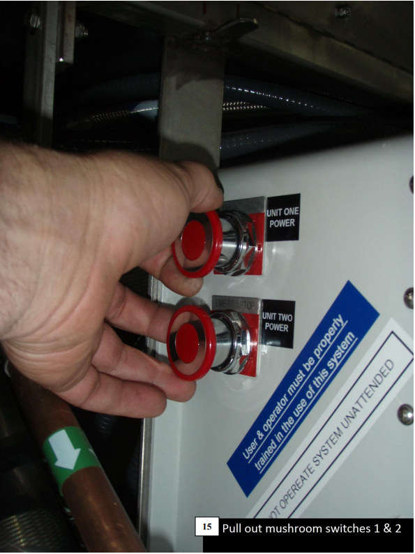
Could result in a Threat to Divers Life
Do Not Operate If Any Part of the System
Does Not Function Properly
Manufacturer and Distributors are not
Responsible for Misuse of this Equipment
TABLE OF CONTENTS
Operations Manual_____________________________________________1
Specifications and Recommendations______________________________4
Pump Set Up__________________________________________________7
Set-Up Procedures_____________________________________________8
Fuel Hook-Up Procedure_______________________________________12
Shutting the System Down______________________________________12
Pre-Operations Checklist_______________________________________13
Maintenance_________________________________________________15
Nozzle Changing Procedure_____________________________________17
Troubleshooting______________________________________________19
Frozen Coil Thawing Procedure_________________________________22
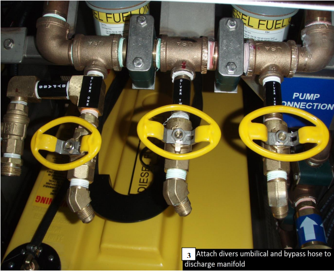
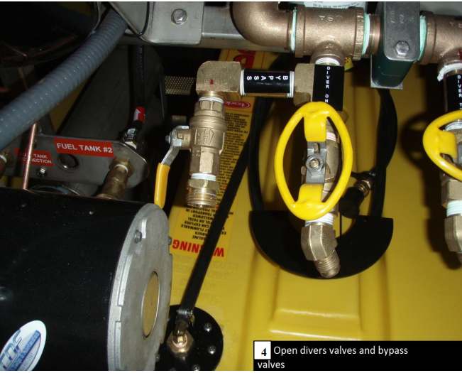
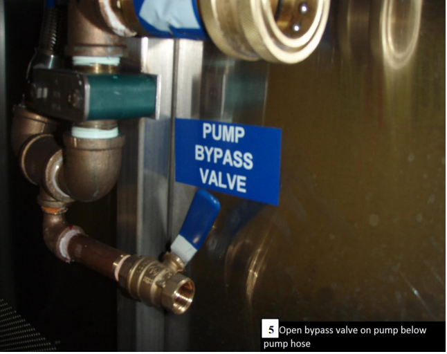
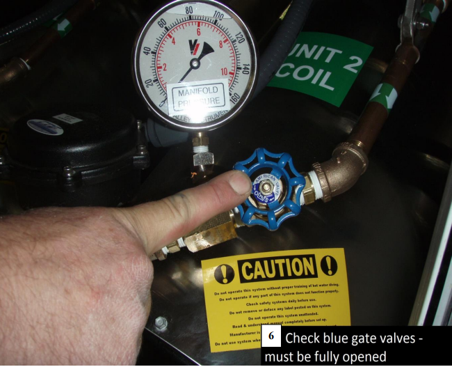
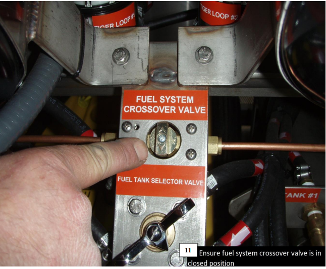
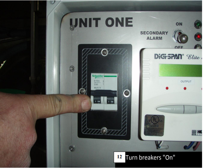
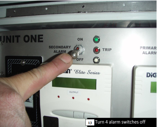
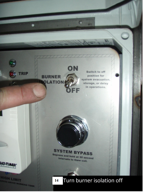
Start Up Procedure (with Pictures)________________________________23
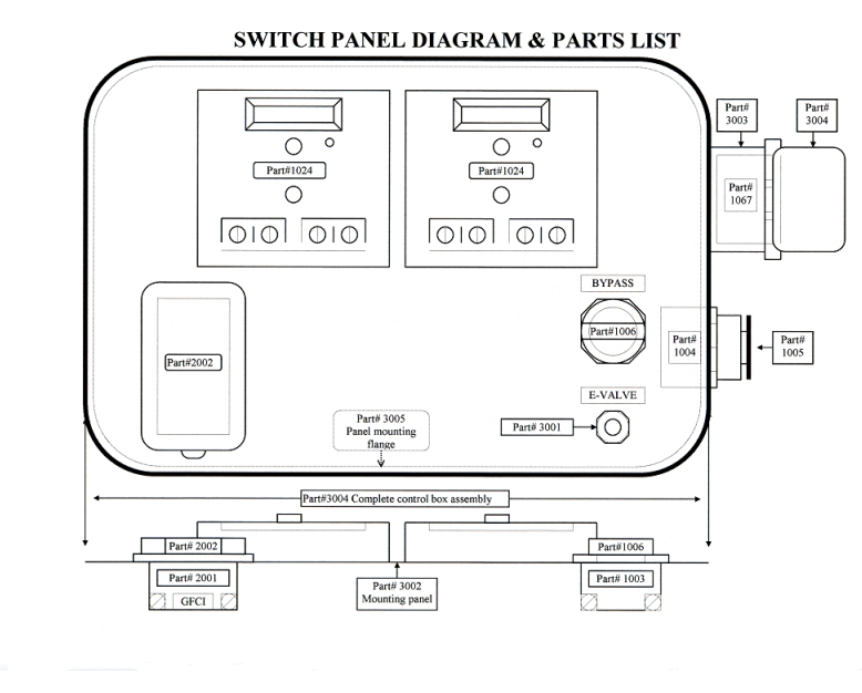
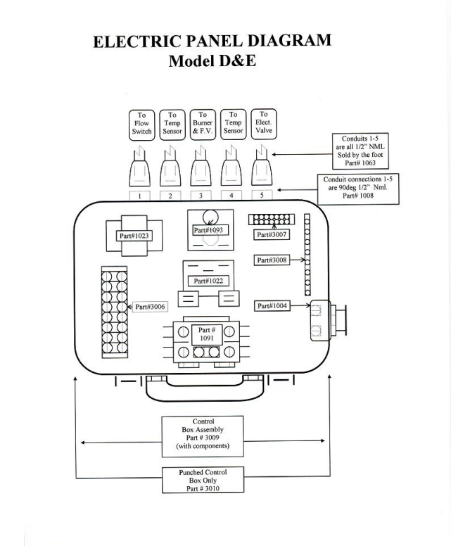
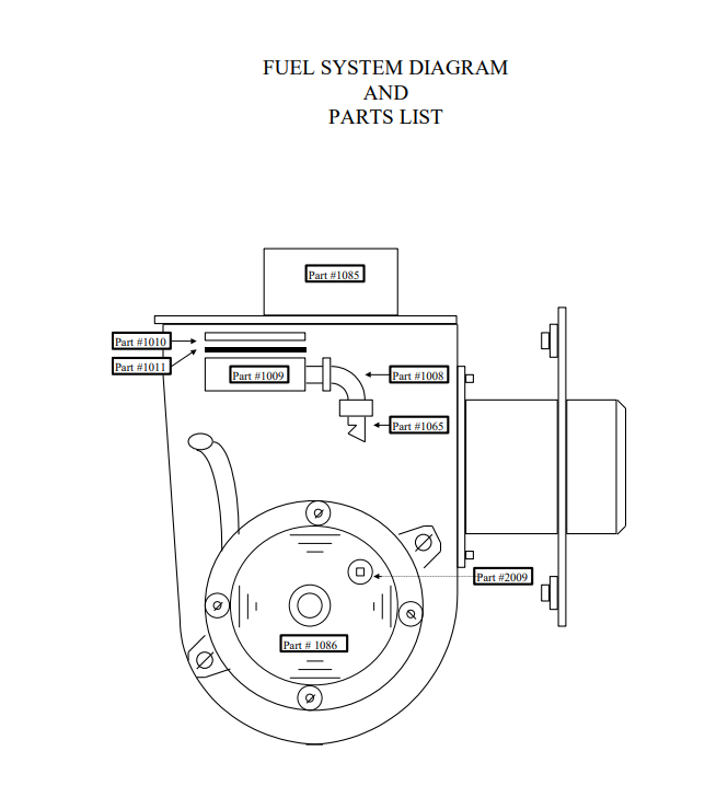
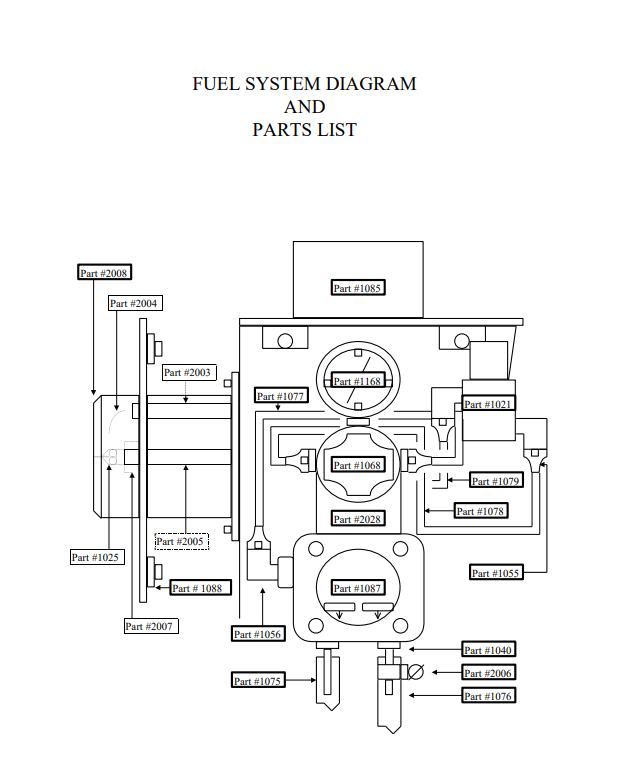
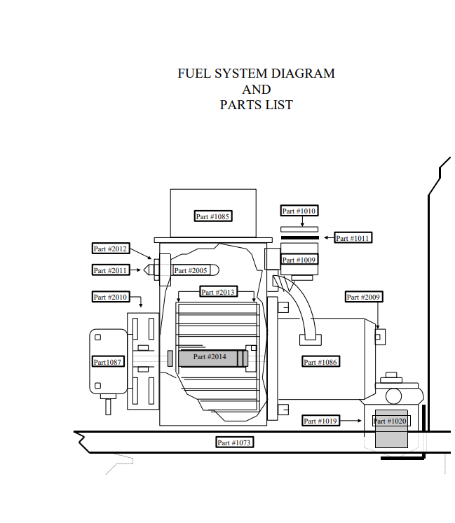
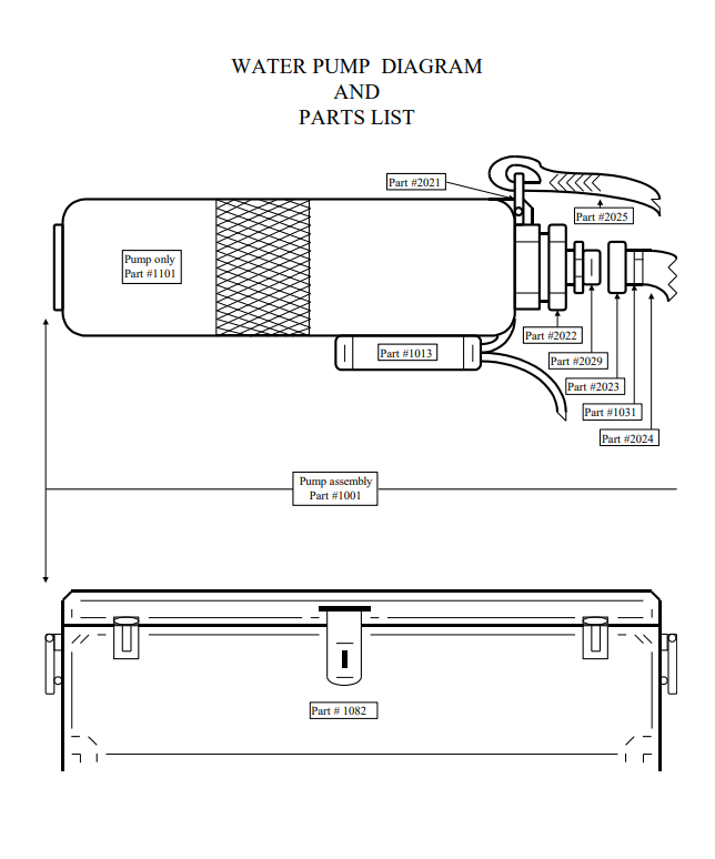
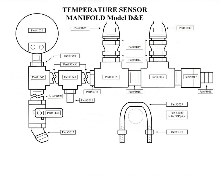
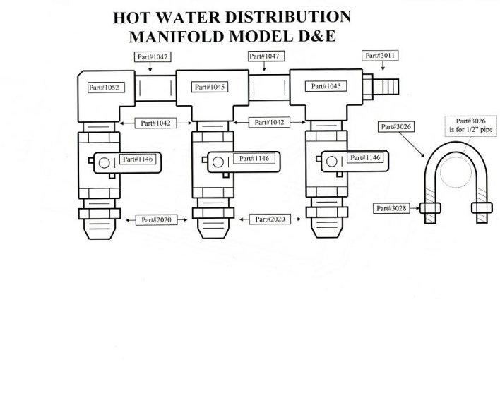
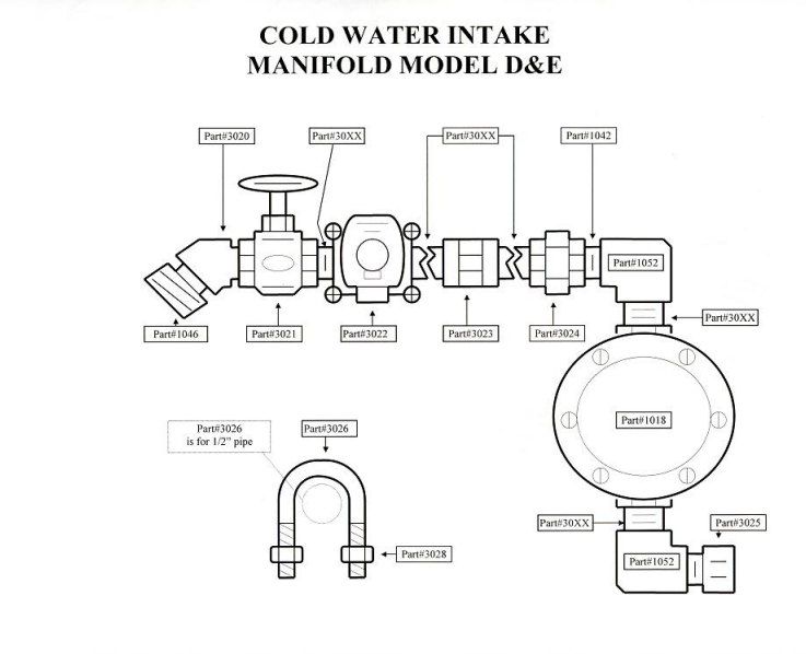
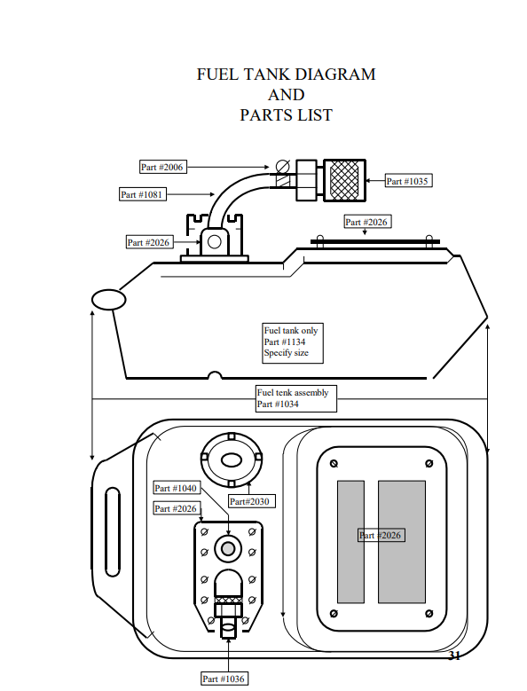
Diagrams and Schematics______________________________________48
Parts List____________________________________________________60
Video Links_________________________________________________64
Monkey Heater Specifications
The Monkey Hot Water Heater System is a complete, lightweight, portable, diver’s water heating system. The system uses a stacked stage submersible pump to provide water to the inlet side of the heater during operations. The system comes ready to operate with the exception of an electrical power source and fuel. The electrical power required to operate the system is 220 VAC, 60Hz, 20 amp, single phase.
The heating unit is mounted and enclosed in a steel, welded, tubular frame. The submersible water pump with a 25-foot umbilical is packed with the system. The heating unit is designed to operate on a 220 VAC, 60Hz, 20-amp, single-phase power source, using #1 or #2 diesel oil.
The unit is rated at 500,000 B.T.U. X 2 an hour output and is capable of heating the outlet water to temperatures in excess of 200° F., depending on the size of the fuel nozzle used and the inlet water temperature. The heater will maintain the set operating output temperature to +/- 1° F.
Fuel consumption is dependent on the size of the fuel nozzle in use. For example, a 1.25 size nozzle will use approximately 1.25 gallons of fuel per hour, while a 2.0 nozzle will use approximately 2 gallons of fuel per hour. (at 100 psi.)
Inlet water is provided to the heater by means of the 11-g.p.m. A stacked stage displacement submersible pump provided with the system. The pump has a maximum combined pumping-lift head capability of 600 feet at 40 psi.
The submersible pump is designed to operate from a 220 VAC, 60Hz, 15-amp, single phase power source. A 15-amp switched outlet is mounted on the heater unit for use with the submersible pump only.
CAUTION!
It is required that the diver uses a hot water suit liner. This will help to eliminate hot spots which could cause burns and provide thermal protection in case of hot water heat loss.
Recommended Suit Injection Temperature
At
2 G.P.M. Flow Rate
For depths of 0 to 100 feet:
Water Temperature to 50° F. = 96° – 98° F.
Water Temperature to 30° F. = 100° – 102° F.
For Depths of 100 to 240 feet.
Water Temperature to 50° F. = 100° – 103° F.
Water Temperature to 30° F. = 103° – 105° F.
The recommended injection temperature is a base line and will need to be adjusted depending on the following factors.
a. Flow Rate (g.p.m.) to the diver. (Higher the rate, lower the temperature.)
NOTE!
The minimum recommended flow rate for 1/2 ID hose is 2 g.p.m. For 5/8” and 3/4” ID hose, the minimum recommended flow rate is 4 g.p.m.
b. Heat Loss from hot water hose.
NOTE!
The heat loss is dependent on: ID and OD of hose, length of hose, ambient air and water, and length of hose in the water.
c. Ambient water temperature.
d. Breathing medium.
e. Breathing gas temperature.
f. Physical condition of diver.
g. Work diver is performing.
Hot Water Hose Heat Loss
On an average, the heat loss for a 300 foot, 1/2” ID, 1¼” OD hot water hose with an injection water temperature of 110° F. and a flow rate of 2 g.p.m., in an ambient water temperature of 35° F., will be about 18° F. (Base Line). The heat loss for a 1/2 ID, 7/8” OD hose, will be about 36° F. (Base Line). Heat loss for the 5/8” and 3/4” ID hot water hose, under the same conditions, will be about 12° F. (Base Line).
If the flow rate is increased by 2 g.p.m., the heat loss will decrease by about 4° F. from the above base line temperature loss.
As the ambient water temperature increases, the heat loss will decrease. The percent of decreased heat loss to water temperature is 40° = 94%, 50° = 86%, 60° = 65%, and 70° = 40%.
Example
To figure the heat loss for a dive in 50° ambient water using 1/2” x 7/8” hot water hose, with a flow rate of 4 g.p.m.:
36° – 4° = 32° x 86% = 27.5° F. heat loss.
To figure what the heater output should be set at, add the recommended suit injection temperature and the hot water heat loss.
These figures are based on extreme ambient weather conditions. If the ambient air is warm, then heat loss will be less and heater output should be decreased.
Nozzle Size
Subtract input water temperature from the final recommended heater output temperature, multiply by the gallons per minute output, multiply by 510 (salt water) or 495 (fresh water), and divide by 100,000. Use the next smaller nozzle if answer does not come out to a nozzle size in the spare parts kit.
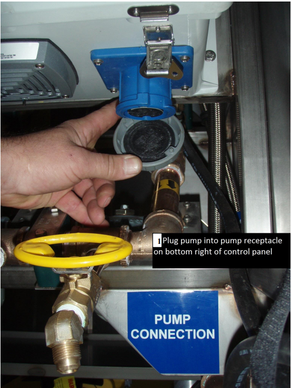
PUMP SET UP (Before Set-Up Procedures)
1. Remove pump from storage.
2. Inspect the watertight electrical connection at the pump and the power cord for damage. If damage is evident, have a qualified electrician repair it before use.
3. It is recommended that the pump is operated at a depth of 3 to 5 feet below Mean Low Water (MLW) or 2 feet from the bottom.
WARNING!
DO NOT OPERATE PUMP IN THE VICINITY OF WORK LOCATION IF PUMPING CONCRETE OR OTHER HAZARDOUS MATERIALS ARE PRESENT IN THE WATER. SUCH MATERIALS CAN DAMAGE THE PUMP AND HEATER SYSTEM AND CAUSE SEVERE BURNS AND SKIN IRRITATIONS TO THE DIVER.
WARNING!
ALWAYS DISCONNECT THE PUMP FROM THE POWER SUPPLY BEFORE SET UP OR REMOVAL FROM THE WATER.
Set-Up Procedures
1. Set up the unit in the area to be used.
2. Pump must be plugged into the outlet provided on the unit, for the unit to function correctly.
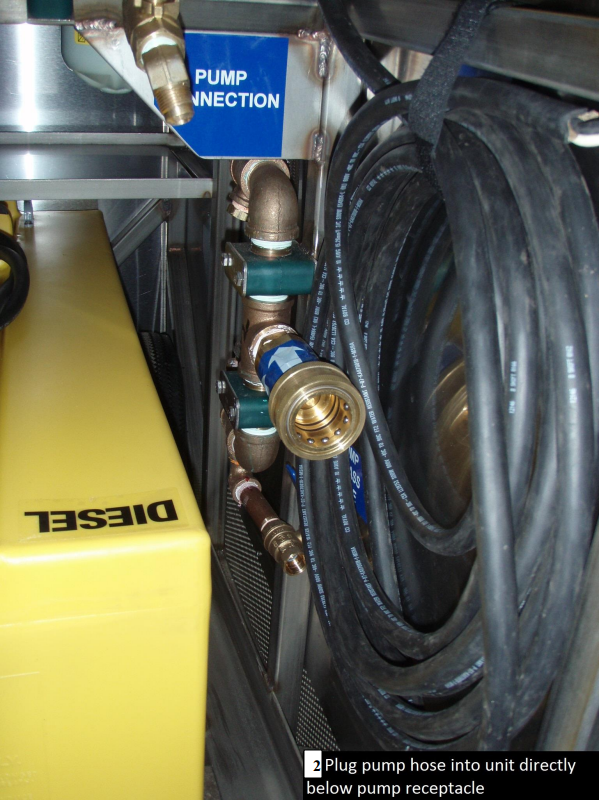
3. Make all of the necessary connections.
a. Connect hose(s) from heater outlet valve(s).
WARNING!
DO NOT OPERATE ANY ELECTRICAL COMPONENT IN THIS SYSTEM WITHOUT USING A GROUND FAULT CIRCUIT INTERRUPTER (GFCI)
3. Fuel unit with either #1 or #2 diesel oil.
4. Make sure a flow of water is present through the system
WARNING!
NEVER OPERATE THE FUEL PRESSURE AT THE REGULATOR LESS THAN 100 PSI. FAILURE TO OBSERVE THIS WARNING WILL RESULT IN INCOMPLETE COMBUSTION, CAUSING EXCESSIVE COIL SOOTING, HARMFUL VAPORS, EXCESSIVE SMOKE AND POSSIBLE FLASHING.
6. Turn unit on, check to make sure burner has fired, and temperature display is functioning.
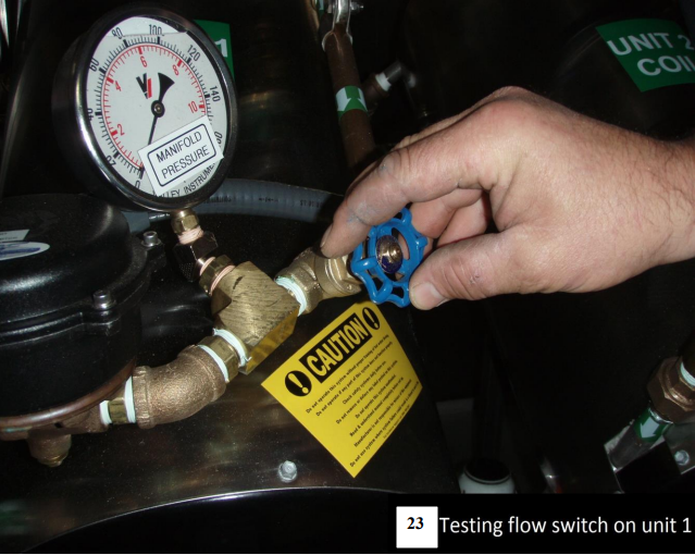
a. Test flow switch.
b. To properly test flow switch function, shut down the water flow to the heater. The unit should shut down if the switch is functioning properly.
NOTE
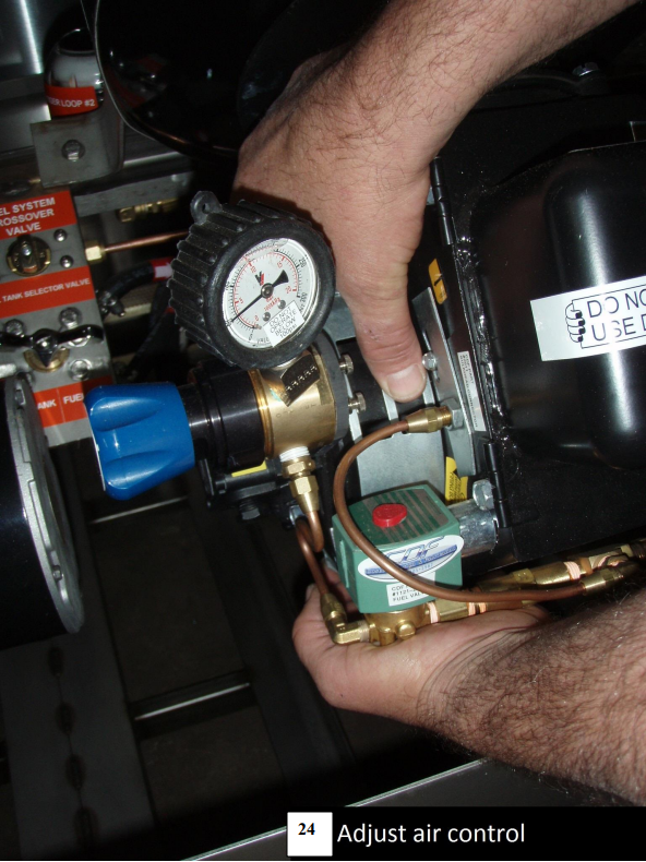
Once burner has fired, observe smoke color. If smoke is white, slightly close vent opening on the burner assembly until smoke disappears. If smoke is black, reverse procedure, slightly opening vent until smoke disappears,
7. Crack open by-pass valve. Set the water flow pressure at 10 psi., using the valve at the units water inlet.
8. Set fuel pressure at the fuel regulator to 120 psi.
9. Allow unit to run 5 minutes or until temperature remains constant on the digital display.
NOTE
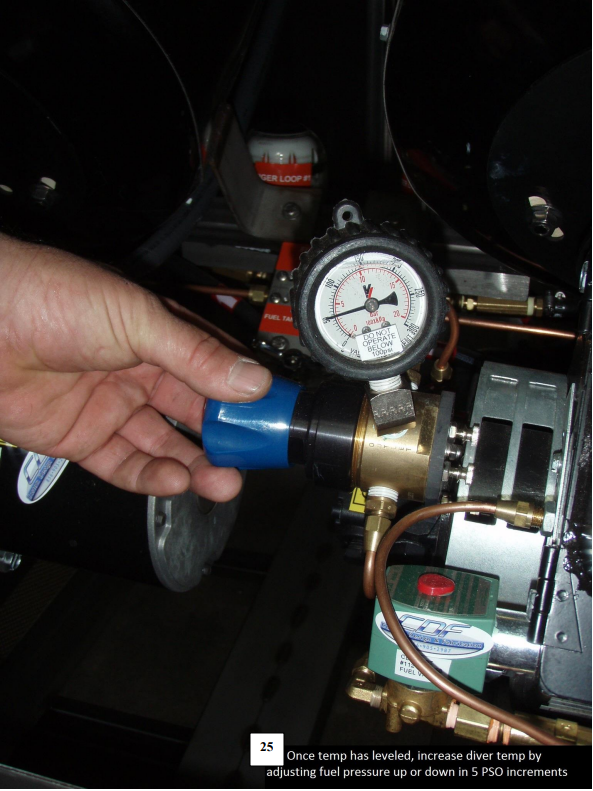
Starting operating temperature is recommended to be at 100° F. and is only a guideline for starting procedure. Fine-tuning of the temperature will be when in actual use. It can be set or changed using the water flow controls or the fuel pressure, set at the regulator.
WARNING!
DO NOT OPERATE THE SYSTEM WITHOUT A DIVER BY-PASS VALVE THAT CAN BE OPERATED BY THE DIVER TO ELIMINATE WATER FLOW IF NECESSARY. IN THE EVENT OF A UNIT MALFUNCTION, SEVERE BURNS MAY OCCUR.
10. Once a comfortable working temperature has been achieved, fine adjustments can be made at the fuel pressure regulator.
11. If all set-up procedures have been followed, you should be able to maintain your operating temperature at +/- 1° F.
HIGH-POINT TEMPERATURE CUT-OFF
After temperature has remained constant on the digital display for 3 minutes, depress the set point button on the control panel. This changes the display to read the present high-point temperature cutoff temperature. Adjustments can be made as follows:
For the primary digital readout
A. Press the set button two times. The display will read Set point.
B. Press the up or down button and the set points will be displayed.
C. Press and hold the up or down button until the desired set point is displayed.
3 degrees F over the working temperature is recommended.
C. Press the set button and then there up key to return to the original display
For your added safety C.D.F. has installed a Secondary High Limit Circuit. This circuit will trip the unit, the pump receptacle, and stop water flow through the unit in the event of a secondary high-limit trip.
NOTE!
IF THE SECONDARY HIGH LIMIT CIRCUIT TRIPS THE WATER TEMPERATURE IN THE SYSTEM MUST DROP 15 DEGREES F BEFORE THE SYSTEM WILL RESTART
The secondary high limit should be calibrated with the primary at the beginning of each dive day or at each time the unit is restarted. Follow the operations manual start up procedures as always and follow these additional steps:
A. After a constant diver working temperature has been achieved set the primary high-limit as described in the manual.
B. Set the secondary high limit in the same manner as the primary, changing the set point temperature to 5 degrees F over the working temperature instead of 3 degrees F.
C. Complete the remaining daily safety systems checkout as described in this operations manual.
WARNING!
SUPPLY PUMP MUST BE CONNECTED TO THE OUTLET PROVIDED ON THE UNIT FOR THE SECONDARY HIGH LIMIT TO FUNCTION CORRECTLY
WARNING!
HIGH-POINT CUT-OFF TEMPERATURE SHOULD BE SET NO HIGHER THAN 2°- 3° F. MAXIMUM OVER WORKING TEMPERATURE TO PREVENT INJURY TO THE DIVER.
FAILURE TO OBSERVE THIS WARNING COULD RESULT IN HEAT EXHAUSTION OR SEVERE BURNS TO THE DIVER.
WARNING!
ALWAYS KEEP CONTROL PANEL COVER CLOSED DURING INCLEMENT WEATHER TO PREVENT DAMAGE TO ELECTRICAL COMPONENTS IN THE SYSTEM.
WARNING!
SHOCK HAZARD! DO NOT TOUCH ANY ELECTRICAL COMPONENTS IN THIS SYSTEM WHEN WET. SEVERE SHOCK OR ELECTROCUTION COULD OCCUR.
WARNING!
COMBUSTIBLE MATERIAL PRESENT. KEEP AWAY FROM SPARK OR OPEN FLAME.
FUEL HOOK-UP PROCEDURE
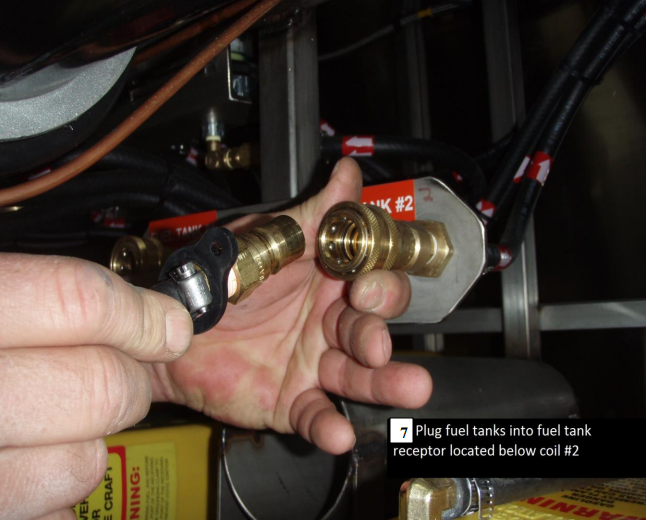
1. Portable fuel containers are provided for your convenience. Each fuel tank has quick connect snap fittings.
2. Connect fuel hose to the tank.
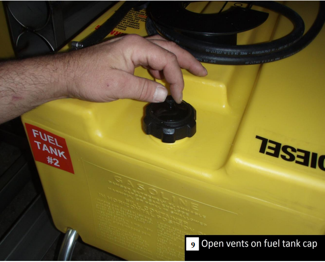
3. OPEN FUEL VENT ON THE FILLER CAP.
4. Unit is self-priming.
SHUTTING THE SYSTEM DOWN
1. Shut the heater off at the control panel.
2. Allow the submersible pump to run until outlet water temperature is between 80° – 90° F.
3. Shut off and unplug the submersible pump.
3. Remove the pump from the water and disconnect all pump fittings. Invert the pump to remove all water.
5. Submerge the pump in a BIO safe solution of anti-freeze.
6. Reconnect the pump to the power supply to flood the system with antifreeze. (Pump umbilical and unit require approximately three gallons of antifreeze.)
7. Free divers umbilical of water and/or flood with anti-freeze. (An evacuation unit can be used to simplify this procedure. Evacuation units are available for any size gallon capacities.)
PRE-OPERATIONS CHECK LIST
1. Hook up water and check Airband
2. Plug in machine
3. Hook up fuel lines
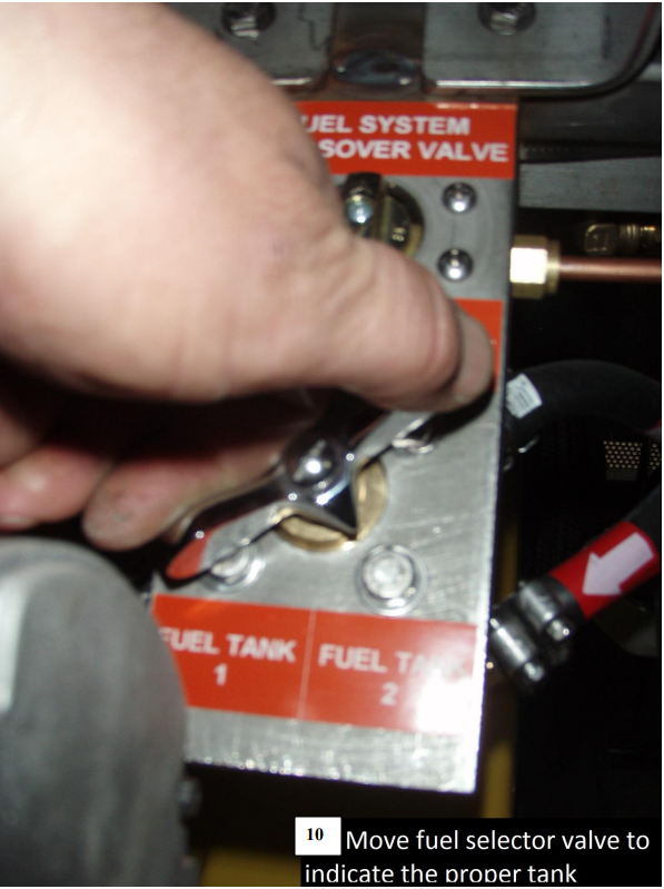
4. Open fuel in tank valve
5. Put on discharge hose
6. Open discharge
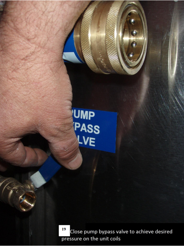
7. Make sure bypass is closed
8. Open water gate valve
9. Turn on water
a. Load regulator about 2 ½ turns
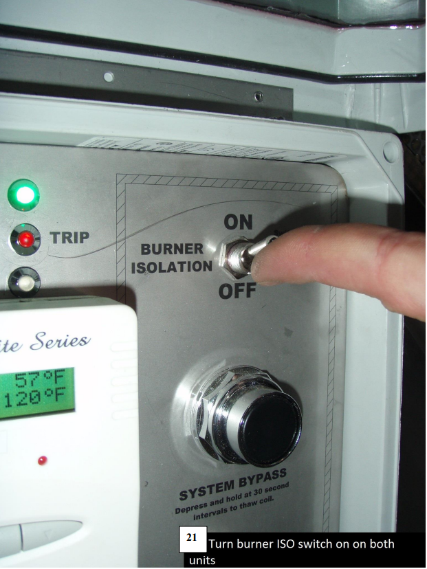
10. Turn on unit
11. Check GFI
12. Check electric valve
a. Water should flow
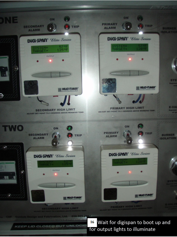
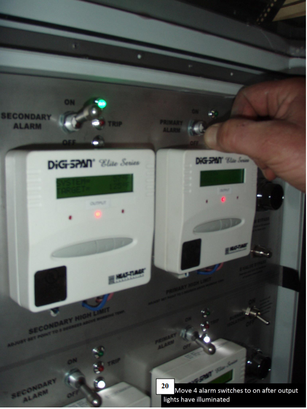
13. Wait for output light to come on
14. Red lights come on
a. Check temperature, both should be within 1-2 degrees of each other
b. Let unit run approximately 5 mins. Unit must level out temperature to
continue
15. Set secondary differential to 15
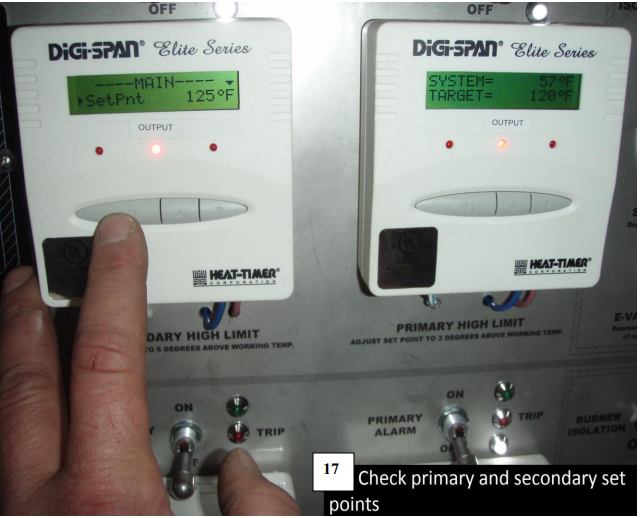
16. Set secondary set point to 125
a. Output light should come on
i . Contactor should close
17. Set primary differential to 1
18. Set primary set point to 120
19. Check flow switch by turning off water using gate valve
a. Unit should shut down
b. IF THE UNIT DOES NOT SHUT DOWN< IMMEDIATELY TURN THE UNIT OFF<
20. Turn water back on
a. Unit should fire in 6 seconds
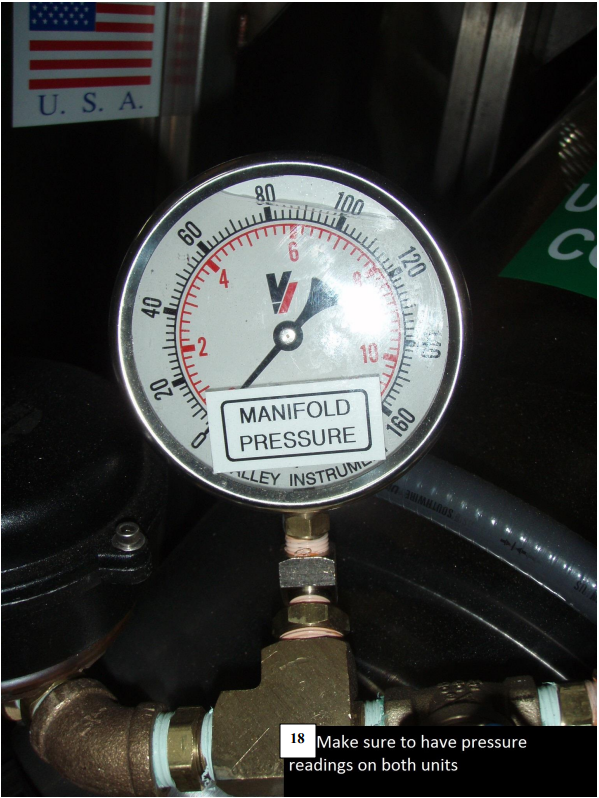
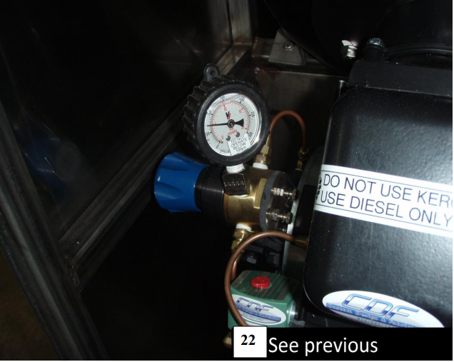
21. Fuel pressure should be 100
a. No smoke
i. If black, open air 1/8” increments
ii. If while close 1/8” increments
22. Rotate fuel regulator clockwise to 200
23. Dial back to 100
a. Check for fuel leaks
24. Check secondary
a. Dial down until unit shuts off
i. ALL functions should stop
ii. No flame
iii. No water
25. Dial secondary set point back up
a. Unit should resume operation to 120-125
b. Let unit run and let temperature level out
i. Should be within 2 degrees
c. If unit cycles raise primary and secondary SP 5 degrees respectively until
unit stops cycling Do not exceed 170 on secondary
26. Reset primary Set Point to 120, 125 in winter
27. Recheck differential to make sure it is 1
a. Burner should shut off
28. Reset secondary SP to 125, 130 in winter
29. Recheck differential to 15
30. At some point when primary is off and secondary is on degrees bypass burner
should fire
a. You can dial down primary to achieve this
31. Turn unit off
32. Cool down by pressing electric valve bypass
33. Shut off water
a. Unhook water supply
34. Blow out with air
a. Not to exceed 100 psi
35. Open all ball valves
a. Drain and close Diver 1
b. Open discharge
36. Pump 1 gallon of antifreeze into each coil.
a. Press electric bypass
37. Blow out unit with air
a. Not to exceed 100 PSI
38. Open all valves
a. Drain and close all valves except gates
39. Disconnect all lines
a. Shut off fuel supply
b. Plug fuel fittings in each other
40. TAKE OFF ATTACHMENT FOR WATER, AIR AND ELECTRIC
NOTE
These daily checks will ensure the unit is functioning correctly.
WARNING!
DO NOT OPERATE UNIT IF ANY COMPONENT IN THE SYSTEM IS NOT FUNCTIONING CORRECTLY. TO DO SO COULD CAUSE SEVERE BURNS TO THE DIVER OR CAUSE DAMAGE TO THE SYSTEM.
WEEKLY MAINTENANCE
1. Disconnect Power Supply
2. Replace any non-working parts, valves, gauges etc.
3. Review safety checklist for unit function.
4. Change fuel filter.
5. Run through the testing a heater procedure.
WARNING!
WHEN SERVICING, BE SURE HEATER IS DISCONNECTED FROM POWER SOURCE TO PREVENT ELECTRICAL SHOCK OR FIRE.
MONTHLY MAINTENANCE
1. Disconnect Power Supply.
2. Replace any non-working parts.
3. Review safety checklist for unit function. (TESTING A HEATER)
4. Change fuel filter.
5. Replace fuel nozzle
6. Inspect coils for soot build up.
7. Inspect fuel tank and fittings for dirt and water inside.
8. Inspect electrodes for damage.
9. Inspect circuits for corrosion and damage.
YEARLY MAINTENANCE
1. Change fuel filter.
2. Change fuel nozzle.
3. Inspect blower for corrosion.
4. Wash heater coil free of soot, using a wire brush or vacuum.
5. Remove 3 nuts from burner mounting flange.
6. Carefully remove burner and set aside. Leave electrical connections and fuel hose intact.
7. Cover with waterproof plastic.
8. Replace gasket on burner flange.
9. Check parts inventory.
a. New fuel filter.
b. Replace lost or used fuel nozzles.
c. Replace hose fitting washers.
d. Replace any lost or worn fittings.
10. Decalcify the coils using “Ryde lime” or compatible decalcifying solution.
WARNING!
DO NOT OPEN ELECTRICAL CLOSURE FITTINGS OR PANEL COVERS. THIS PROCEDURE SHOULD ONLY BE DONE BY A QUALIFIED ELECTRICIAN.
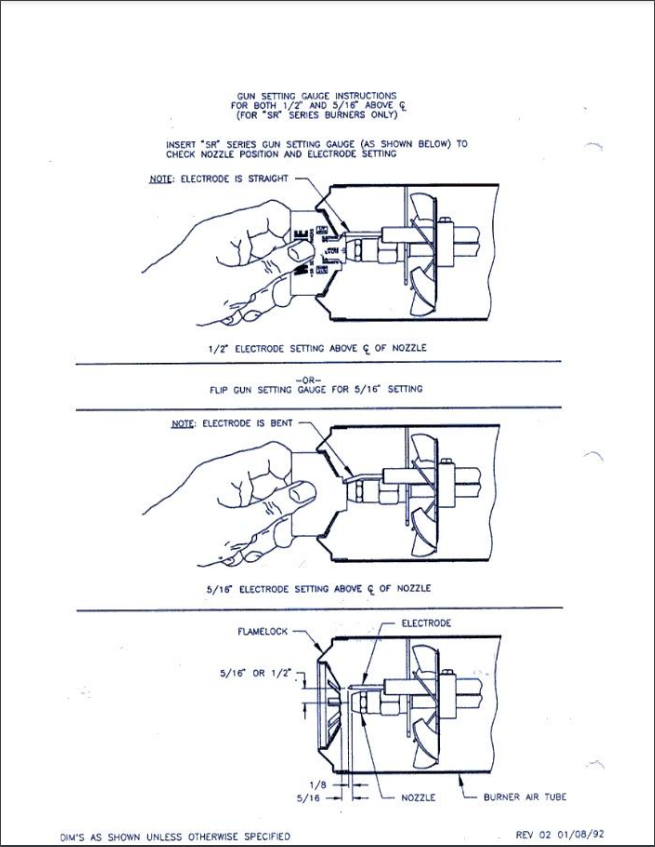
NOZZLE CHANGING PROCEDURE
1. Disconnect Power Supply.
2. Close air vent on burner adjustment band.
3. Loosen the flare nuts and remove the fuel line between the solenoid valve and nozzle pipe. Set aside. Caution! Be careful not to drop the nut into the air vent!
4. Remove nozzle pipe retaining nut from nozzle pipe and set aside.
5. Loosen the coil clamp located on the other side of the coil and open the burner lid. Carefully slide the nozzle pipe assembly downward and out until the assembly becomes free and lifts out.
Caution! Be careful not to damage the ceramic insulators on the electrodes.
6. Replace the nozzle with the desired size.
7. Reset the electrodes or replace if damaged.
8. Replace the nozzle pipe assembly. Re-assemble all components by reversing the disassembly procedures. Open air band on the burner assembly. Make air adjustments following set-up procedures.
BE CAREFUL NOT TO MOVE ELECTRODE SETTINGS