Limited one-year warranty

This Heat-Timer device was thoroughly tested for defects and workmanship before leaving our factory. We do warrant the equipment to be free of defects under normal use for a period of one year from the date of installation. Transportation charges for factory repairs must be prepaid. Damage to the Heat-Timer device or any of its components due to misuse, abuse, improper installation, or caused by power failures, fire, flood, or lightning are not covered by this warranty. The company assumes no liability for indirect or consequential damages of any nature. This Heat-Timer warranty applies only to the original purchaser/user, is not assignable or transferable, and does not cover damage to the device occurring in shipment. Any service, repairs, modifications or alterations to the unit not expressly authorized by the company will invalidate the warranty. This warranty is in lieu of all other warranties expressed or implied.

Mounting the Controller

The SPC DIGI-Elite is designed to mount on a 1900 (4”x4”) electrical box.• If the SPC-Elite is to be panel mounted, or if additional room is needed use the Plastic Wiring Enclosure (HT# 929135-00 Switch) or (HT# 929137-00 without a Switch).
• Locate the SPC-Elite in a convenient location near the unit to be controlled.
• Partially unscrew the Display Cover Mounting screws. This allows for its removal.
• Lifting the Display Section away from the base will unplug the Connection Socket from the Base section.
• Proceed with the power and output wiring instructions.
• Mount the SPC-Elite away from excessive heat or cold. Ambient operating temperature is from 20 to 120°F.
• Mount Display Section back to the Base Section. Tighten the Display Cover Mounting Screws.

Wiring Power Input

The SPC-Elite is designed to accept ONLY A SINGLE POWER SOURCE. It can be wired to either 120VAC using the two Black wires or 24VAC using the right most two terminals on the terminals block on bottom of the control. Heat Timer recommends the installation of a Surge Suppressor and a Power Switch before the Power Line connection for safety and ease of service.

120VAC

• Attach line voltage, 120VAC, to the two Black wires extending from the back of the SPC-Elite. Remember to use the power line from a different source than the equipment being controlled.

24VAC

• Use a dedicated transformer with at least a 5VA output.
• Bring 24VAC to the two right most screws on the front of the SPC-Elite marked 24VAC and COM.

Installing and Wiring Temperature Sensor Inputs

(T1, COM (-30°F-250°F), T3± ( 220°F-900°F))

A variety of sensor inputs can be connected to the SPC-Elite series depending on the model and sensors provided. However, all temperature sensors are wired the same way. Each SPC-Elite comes with the sensors it is designed to work with
• The temperature sensor wires can be extended up to 500′ by splicing with 18 gauge shielded wire.
• Do not run sensor wires in conduit with line voltage.
• If measuring liquid temperature, the sensor should be inserted into a 3/8″ ID well
(HT#904011 or equivalent).
• The SPC-Elite will operate based on the temperature it reads at the sensor location.
Therefore, select a sensor location that is representative of the entire system.
• In temperature applications, polarity is not observed. Either wire from the sensor can be connected to either sensor input.
• Connect the Shield of each sensor at the control side to the respective COM terminal.
• T1, COM Used for Temperature sensors reading up to 250˚F/121˚C. Sensor Shield is connected to the COM Terminal
• T2, COM Not Used.
• T3+,T3- Used for High Temperature sensors reading up to 930˚F/499˚C. Sensor Shield is connected to the T3- Terminal

Installing and Wiring a Pressure or Vacuum Sensor

(P+, P-)

• Attach a 1/4” brass isolation tube (pigtail) to the steam header.
• Screw the pressure or Vacuum sensor to the pigtail. The sensor has 1/4” NPT tapered threads.
• The sensor wires can be extended up to 500’ by splicing with 18 gauge shielded wire.
• Do not run sensor wires in conduit with line voltage.
• The SPC-Elite will operate based on the pressure or vacuum sensor reading. Therefore, select a sensor location that is representative of the entire system.
• The sensor’s BLACK wire should be connected to the terminal marked P (-).
• The RED wire from the sensor should be connected to the terminal marked P (+).

Connecting the Enable/Disable

(EXT+, EXT-)

• The EXT terminals can be used to enable or disable the system by connecting it to either a thermostat or external control.
• The EXT input should be dry contact only.
• Polarity is not important. Either wire from the thermostat can be connected to either EXT terminals.
• If no thermostat or control is connected to the EXT terminals, leave the jumper supplied as a contact to the terminals.
• No outputs will be active unless the EXT terminals are closed.

Button and Navigating Menus

The SPC-Elite has three buttons.

• The SET button function varies. When the Default Screen is displayed, pushing the SET Button views the MENU. When in the Menus and settings, the SET Button accepts the selected entry or setting value.

• When in the menus, the Up and Down buttons will scroll through the menu options. They can be used to change the setting of a specific function. i.e. change the Set Point, Differential, or System Trim.

• At the end of every operation menu there is a option that allows the user to go back one menu level. If the SET Button was held down for three seconds on the option, the display will go back to the default screen.

Startup Options

Whenever the control is started for the first time or after a manual reset, it will initiate its operation with the Startup Menu. Moreover, the Startup menu can be accessed by selecting it from the operation menu. An option must be selected in each screen in the Startup Menu to move to the next level.

Standard

Options: English, Metric

MENU//Standard

Due to the large variety of inputs available to connect to the SPC-Elite, this option helps in narrowing down the sensor type options.
• If English is selected, sensor types in ˚F (Fahrenheit), PSI (Pounds/Square inch), Hg (Inches of Mercury for Vacuum) will be available.
• If Metric is selected, sensor types in ˚C (Celsius), MPa (Million Pascal), mm (Millimeter of Mercury for Vacuum) will be available.
• %RH (Relative Humidity) will be available in both options

Sensor Type

Options: Temp.250˚F/121˚C, Temp.900˚F/480˚C, Pres. 30PSI/0.25MPa, Pres. 100PSI/0.60MPa,
Pres. 200PSI/1.0MPa, Pres. 300PSI/1.6MPa, Vac. 30Hg/760mm, and Relative Humidity %RH
Default: Temp.250˚F/121˚C

MENU//Standard/Sensor Type

The Sensor Type available options depend on the Standard option selected from the previous menu.

Control Mode

Options: Heat-BreakOnRise, Cool-MakeOnRise                                                 Default: Heat-BreakOnRise

MENU//Standard/Sensor Type/Control Mode

The SPC-Elite can operate in either mode.
• In Heat-Break-On-Rise mode the relay will energize when the sensor value is below the set point.
• In Cool-Make-On-Rise mode the relay will de-energize when the sensor value is below the set point.

Sensor Fault

Options: All Off, All On                                                                                       Default: All On

MENU//…./Sensor Fault

The Sensor Fault will determine the operating status of the relay when a sensor reads Short or Open. On sensor fault the Set Point will indicate FAULT TGT=ON or OFF to indicate the condition of the output and the Sensor will read SYSTEM=OPEN or SHORT to indicate the condition of the sensor

Manually Resetting the Control to Defaults

To Reset the SPC-Elite control to its original factory defaults, power down the control. Hold down the SET and DOWN buttons while powering the control back up until the Loading Default Values screen appears. The Display will direct you to the Startup menu after the defaults are loaded to program the control as if for the first time.

Operating Menu Options

To enter the operating menu functions, click the SET button.

Set Point

Options: Varies based on Sensor Type. See “Sensor Type Settings and Terminals”

MENU/SetPnt

The Set Point (Target) is the temperature, pressure, vacuum, or relative humidity the SPC-Elite will use to control the system. It will be displayed on the default screen as the Target.

Differential

Options: Varies based on Sensor Type. See “Sensor Type Settings and Terminals”

MENU//Diff

The differential controls how many degrees the system can fluctuate around the set point. It is used to prevent short cycling of the unit being controlled. A smaller Differential setting will normally result in tighter control of the set point but will tend to increase the frequency of fluctuation in the system. Larger Differential values will reduce output short cycling, but the system will be allowed to vary further from the set point value.

System Trim

Options: Varies based on Sensor Type

MENU//SysTrm

The System Trim value adjusts the sensor reading using positive or negative values. It allows you to calibrate the sensor by the number of units selected.

Sensor Type Settings and Terminals

Heating and Cooling Operation

The SPC-Elite can operate in either heating or cooling applications. Select the proper application from the Startup menu.
• In heating applications, the SPC-Elite control will use the Set Point less the Differential as a starting point when temperature or sensor reading is dropping. Then, it will keep the relay energized as long as the sensor is below the Set Point (Target).
• When the system value increases in heating applications, the relay will remain energized until the Set Point (Target) is reached. Then, it will de energize.
• In cooling applications, the SPC-Elite control will use the Set Point plus the Differential as a starting point when temperature is increasing. It will energize the output relay as long as the sensor is above the Set Point (Target).
• When the system value falls in cooling applications, the relay will remain energized until the Set Point (Target) is reached. Then, it will de-energize.

Output Light

The SPC-Elite has three lights, however,

only the middle output light is used.

It follows the relay operation. Whenever,

Output Light is ON, the relay is energized.

Enable/Disable Input

The SPC-Elite will operate in heating or cooling modes only if the EXT- and EXT+ terminals are shorted. If no external equipment or switch is connected to these terminals, leave the factory installed jumper.
When the terminals are OPEN, the Target will display TSTAT OPEN.

Troubleshoot

No Display:

First, make sure that the Sensor Type selected matches the sensor used. Also, make sure that the sensor is connected to the respective input terminals. If control reads OPEN, the SPC-Elite either does not see a sensor connected or the sensor reading is below the sensor operating range. Check the sensor wires are connected from the sensor to the SPC-Elite controller. If SHORT, the SPC Elite either sees a short across the input terminals or the sensor reading is above its operating range. Remove the sensor wires from the SPC-Elite terminals, the display should read OPEN. If the display does not change to OPEN, the SPC-Elite may be damaged. Otherwise, follow steps for Incorrect Temperature Display for temperature sensors or Incorrect pressure or Vacuum Display for all transducers

Incorrect Temperature Display:

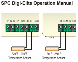
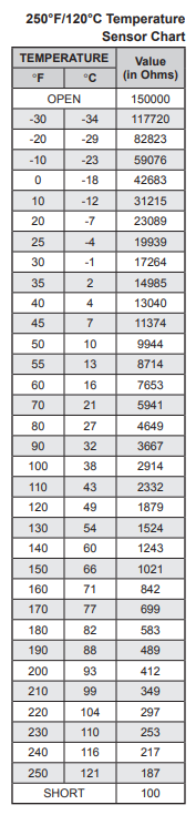
Remove the wires from the SENSOR screws. The display should change to read OPEN. If it doesn’t, the SPC-Elite may be damaged. For temperature, take an ohm reading across the detached sensor wires. The ohm reading should correspond to the chart on the right. If the ohm reading is significantly different, the sensor may be damaged.

Incorrect High Temperature Display:

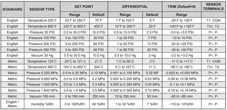
If using a High Temperature sensor on T3±, then calibrate the sensor using a 2K Ohm resistor. First measure the resistor accuracy using an Ohm meter. If correct, then connect the resistor to terminals T3±. The display should read 511˚F/266˚C. If it does not then change the System Trim function in the Maintenance menu until you get 511˚F/266˚C. Then reinstall the sensor wires back.

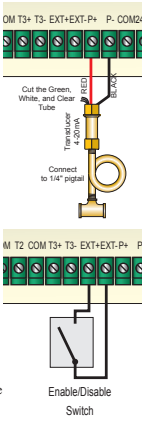
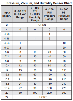
Incorrect Pressure or Vacuum Display:

Make sure that the pressure setting selected matches the pressure transducer connected to the SPCElite control. If it does, then use a current multi-meter and set it to read mA and put it in series with the sensor. Match the ohm reading to the pressure table below. If current does not match the actual pressure, use the System Trim from the Maintenance Menu to correct it. If the difference is larger than the System Trim range, then the pressure or vacuum transducer is damaged. Remember that Pressure and Vacuum transducers are susceptible to static electricity. Thus, reduce excessive manual handling prior to transducer installation

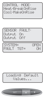
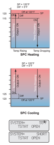
Output Red Light does not come on at the desired temperature:

Check the set point and differential values. In a heating application, the Red light will not come on until the sensor value drops below the set point minus the differential. In a cooling application, the Red light will not turn off until the sensor value rises above the set point plus the differential.

SPC-Elite does not activate the output:

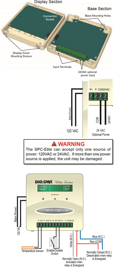
First remove all connections to the Red, White, and Blue output wires. If the Output Red Light is on, the relay should be energized; the Red to White wires should be closed, and the Red to Blue wires should be open. If the Output Red Light is off, the relay should be de-energized; the Red to White wires should be open, and the Red to Blue wires should be closed. If the above two conditions are met, the SPC-Elite is working normally. Check the unit the SPC-Elite is controlling.

Specifications

Voltage Input: . . . . . . . 120 VAC 60 Hz(2 Black wires) /24VAC 60 Hz (24VAC terminals) (Only One Power Source)
Power Consumption: . . . . . . . . . . . . . . . . . . . . . . . . . . . . . . . . . . . . . . . . . . . . . . 3 VA Max
Operating Temperature: . . . . . . . . . . . . . . . . . . . . . . . . . . . . . . . . . . . . 20°F/-7°C to 120°F/49°C
Operating Humidity: . . . . . . . . . . . . . . . . . . . . . . . . . . . . . . . . . . . . . . . . . . . . . 20% to 80%
Dimensions: . . . . . . . . . . . . . . . . . . . . . . . . . . . . . . . . . . . . . . . . . . . . . . . 4″W x 4″H x 2½”
Shipping Weight: . . . . . . . . . . . . . . . . . . . . . . . . . . . . . . . . . . . . . . . . . . . . . . . . .1 pound
Output: . . . . . . . . . . . . . . . . . . . . . . . . . . . . . . . . 1 S.P.D.T (White+Red = N.O.), (Blue+Red = N.C.)
Output Relay Ratings: . . . . . . . . . . . . . . . . . . . . . . . 1 Amp inductive, 6Amp resistive at 120 VAC 60 Hz
Operating Modes: . . . . . . . . . . . . . . . . . . . . . . . . . . . . . Heat (Break on Rise) or Cool (Make on Rise)
Sensor Fault Operating Options: . . . . . . . . . . . . . . . . . . . . . . . . . . . . . . . . Output On or Output Off
Temperature Ranges: . . . . . . . . . . . from -30˚F (-34˚C) to 250˚F (121˚C) or from 220˚F (104˚C) to 900˚F (480˚C)
Pressure Ranges: . . . . PSI (0-30PSI, 0-100 PSI, 0-200PSI, 0-300PSI) or MPa (0.25MPa, 0.60MPa, 1MPa, 1.6MPa)
Vacuum Range: . . . . . . . . . . . . . . . . . . . . . . . . . . . . . . . . . . . . . . . . . . . . . 30Hg or 760mm
Humidity Range: . . . . . . . . . . . . . . . . . . . . . . . . . . . . . . . . . . . . . . . . . . . . . 0% to 100% RH
Display: . . . . . . . . . . . . . . . . . . . . . . . . . . . . . . . . . . . . . . Alphanumeric (2 rows x 16 char. each)
LED: . . . . . . . . . . . . . . . . . . . . . . . . . . . . . . . . . . . . . . Middle LED representing the Output relay
Buttons: . . . . . . . . . . . . . . . . . . . . . . . . . . . . . . . . . . . . . . . . . . . . . . . . 3 (Set, Up, Down)
Enable/Disable: . . . . . . . . . . . . . . . . . . . . . . . . . . . . . . . . . . . . . . . . . . Terminals EXT+, EXT